- 您现在的位置:买卖IC网 > Sheet目录987 > LD4T06P0 (Red Lion Controls)TIMER 6 DIGIT 4.0" 120VAC RED
�� �
�
�Sending� Serial� Commands� and� Data�
�When� sending� commands� to� the� meter,� a� string� containing� at� least� one�
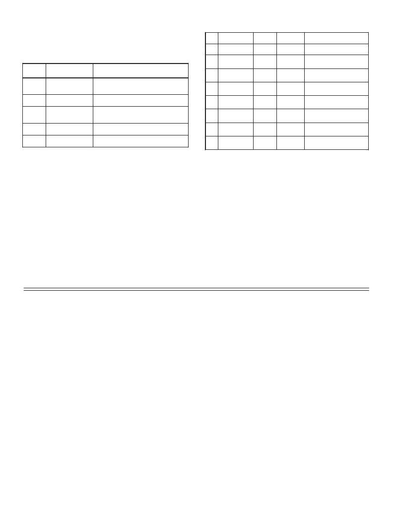
�Register� Identification� Chart�
�command� character� must� be� constructed.� A� command� string� consists� of� a�
�command� character,� a� value� identifier,� numerical� data� (if� writing� data� to� the�
�meter)� followed� by� a� command� terminator� character,� *� or� $.�
�Command� Chart�
�ID�
�A�
�B�
�Value�
�Description�
�Timer�
�Cycle� Counter�
�MNEMONIC�
�TMR�
�CNT�
�Applicable�
�Commands�
�T,� V,� R�
�T,� V,� R�
�Transmit� Details� (T� and� V)�
�6� digit,� per� Timer� Range�
�5� digit�
�Command� Description�
�Notes�
�C�
�Timer� Start�
�TST�
�T,� V�
�6� digit,� per� Timer� Range�
�N�
�T�
�V�
�R�
�P�
�Node� (meter)�
�Address� Specifier�
�Transmit� Value� (read)�
�Value� Change� (write)�
�Reset�
�Block� Print� Request�
�(read)�
�Address� a� specific� meter.� Must� be� followed�
�by� one� or� two� digit� node� address.� Not�
�required� when� node� address� =� 0.�
�Read� a� register� from� the� meter.� Must� be�
�followed� by� a� register� ID� character.�
�Write� to� register� of� the� meter.� Must� be�
�followed� by� a� register� ID� character� and�
�numeric� data.�
�Reset� a� value� or� the� output.� Must� be� followed�
�by� a� register� ID� character�
�Initiates� a� block� print� output.� Registers� in� the�
�print� block� are� selected� in� Print� Options.�
�D�
�E�
�F�
�G�
�H�
�Timer� Stop�
�Counter� Start�
�Setpoint� ON�
�(Reset� Output)�
�Setpoint� OFF�
�Setpoint�
�Time-out�
�TSP�
�CST�
�SPT�
�SOF�
�STO�
�T,� V�
�T,� V�
�T,� V,� R�
�T,� V�
�T,� V�
�6� digit,� per� Timer� Range�
�5� digit�
�per� Setpoint� Assignment,�
�same� as� Timer� or� Counter�
�per� Setpoint� Assignment,�
�same� as� Timer� or� Counter�
�6� digit,� mm.ss.ss� format�
�Command� String� Construction�
�The� command� string� must� be� constructed� in� a� specific� sequence.� The� meter�
�does� not� respond� with� an� error� message� to� illegal� commands.� The� following�
�procedure� details� construction� of� a� command� string:�
�1.� The� first� 2� or� 3� characters� consist� of� the� Node� Address� Specifier� (N)� followed�
�by� a� 1� or� 2� character� node� address� number.� The� node� address� number� of� the�
�meter� is� programmable.� If� the� node� address� is� 0,� this� command� and� the� node�
�address� itself� may� be� omitted.� This� is� the� only� command� that� may� be� used� in�
�conjunction� with� other� commands.�
�2.� After� the� optional� address� specifier,� the� next� character� is� the� command�
�character.�
�3.� The� next� character� is� the� register� ID.� This� identifies� the� register� that� the�
�command� affects.� The� P� command� does� not� require� a� register� ID� character.� It�
�prints� all� the� active� selections� chosen� in� the� Print� Options� menu� parameter.�
�4.� If� constructing� a� value� change� command� (writing� data),� the� numeric� data� is�
�sent� next.�
�5.� All� command� strings� must� be� terminated� with� the� string� termination�
�characters� *� or� $.� The� meter� does� not� begin� processing� the� command� string�
�until� this� character� is� received.� See� timing� diagram� figure� for� differences� in�
�meter� response� time� when� using� the� *� and� $� terminating� characters.�
�Receiving� Data� From� The� Meter�
�Data� is� transmitted� from� the� meter� in� response� to� either� a� transmit� command�
�(T),� a� block� print� request� command� (P)� or� a� User� Input� print� request.� The�
�response� from� the� meter� is� either� a� full� field� transmission� or� an� abbreviated�
�transmission,� depending� on� the� selection� chosen� in� Module� 5.�
�Full� Field� Transmission�
�Command� String� Examples:�
�1.� Node� address� =� 17,� Write� 350� to� the� Setpoint� On� value�
�String:� N17VF350$�
�2.� Node� address� =� 5,� Read� Timer� value,� response� time� of� 50� msec� min�
�String:� N5TA*�
�3.� Node� address� =� 0,� Reset� Setpoint� output�
�String:� RF*�
�4.� Node� address� =� 31,� Request� a� Block� Print� Output,� response� time� of� 2� msec� min�
�String:� N31P$�
�Transmitting� Data� to� the� Meter�
�Numeric� data� sent� to� the� meter� must� be� limited� to� Transmit� Details� listed� in� the�
�Register� Identification� Chart.� Leading� zeros� are� ignored.� The� meter� ignores� any�
�decimal� point� and� conforms� the� number� to� the� appropriate� display� format.� (For�
�example:� The� Timer� range� is� set� for� tenths� of� a� second� and� 25� is� written� to� the�
�Timer� Start� register.� The� value� of� the� register� is� now� 2.5� seconds.� In� this� case,�
�write� a� value� of� 250� to� equal� 25.0� seconds).�
�Note:� Since� the� meter� does� not� issue� a� reply� to� value� change� commands,� follow�
�with� a� transmit� value� command� for� readback� verification.�
�requested� value� with� decimal� points� positioned� for� the� selected� timer� range.� The�
�data� within� bytes� 9� to� 18� is� right-aligned� with� leading� spaces� for� any� unfilled�
�positions.�
�The� end� of� the� response� string� is� terminated� with� a� <CR>� and� <LF>.� After� the�
�last� line� of� a� block� print,� an� extra� <SP>,� <CR>� and� <LF>� are� added� to� provide�
�separation� between� the� print� blocks.�
�Byte�
�Description�
�Abbreviated� Transmission�
�1,� 2�
�3�
�4-6�
�7-18�
�19�
�20�
�21�
�2� byte� Node� Address� field� [00-99]�
�<SP>� (Space)�
�3� byte� Register� Mnemonic� field�
�12� byte� data� field;� 9� bytes� for� number� and� three� bytes� for� decimal�
�points�
�<CR>� (carriage� return)�
�<LF>� (line� feed)�
�<SP>*� (Space)�
�Byte�
�1-12�
�13�
�14�
�15�
�16�
�17�
�Description�
�12� byte� data� field,� 9� bytes� for� number� and� three� bytes� for�
�decimal� points�
�<CR>� (carriage� return)�
�<LF>� (line� feed)�
�<SP>*� (Space)�
�<CR>*� (carriage� return)�
�<LF>*� (line� feed)�
�22�
�23�
�<CR>*� (carriage� return)�
�<LF>*� (line� feed)�
�*� These� characters� only� appear� in� the� last� line� of� a� block� print.�
�The� abbreviated� response� suppresses� the� node� address� and� register� mnemonic,�
�leaving� only� the� numeric� part� of� the� response.�
�*� These� characters� only� appear� in� the� last� line� of� a� block� print.�
�The� first� two� characters� transmitted� are� the� meter� address.� If� the� address�
�assigned� is� 0,� two� spaces� are� substituted.� A� space� follows� the� meter� address� field.�
�The� next� three� characters� are� the� register� mnemonic,� as� shown� in� the� Register�
�Identification� Chart.�
�The� numeric� data� is� transmitted� next.� The� numeric� field� (bytes� 7� to� 18)� is� 12�
�characters� long.� When� a� display� overflow� exists� for� a� requested� timer� or� cycle�
�counter� value,� an� *� (used� as� an� overflow� character)� replaces� a� space� in� byte� 7.�
�Byte� 8� is� always� a� space.�
�The� remaining� ten� positions� of� this� field� consist� of� seven� positions� for� the�
�12�
�Meter� Response� Examples:�
�1.� Node� address� =� 17,� full� field� response,� Cycle� Counter� =� 875�
�17� CNT� 875� <CR><LF>�
�2.� Node� address� =� 0,� full� field� response,� Setpoint� On� value� =� 250.5�
�SPT� 250.5<CR><LF>�
�3.� Node� address� =� 0,� abbreviated� response,� Setpoint� On� value=� 250,� last� line� of�
�block� print�
�250<CR><LF><SP><CR><LF>�
�发布紧急采购,3分钟左右您将得到回复。
相关PDF资料
LFSTBEB7361
BOARD DEV ACCELEROMETER MMA7361L
LFSTBEB7455
BOARD DEV ACCELEROMETER MMA7455L
LFSTBEB8450
BOARD DEV ACCELEROMETER MMA8450
LFSTBEB845X
EVAL BOARD FOR MMA845XQ
LH1518AT
RELAY SSR SPST 250V 300MA 6DIP
LI12-1A79
RELAY REED SPST 1A 12V
LK1AF-24V
RELAY GEN PURPOSE SPST 5A 24V
LKG1AF-24V-16-1
RELAY GEN PURPOSE SPST 16A 24V
相关代理商/技术参数
LD50
制造商:General Tools 功能描述:Deluxe Lightning Detector 制造商:General Tools 功能描述:DETECTOR LIGHTNING
LD-50
制造商:API TECHNOLOGIES 功能描述: 制造商:API Technologies Corp 功能描述:
LD5000
制造商:WTE 制造商全称:Won-Top Electronics 功能描述:50A 10mm LUCAS TYPE PRESS-FIT DIODE
LD5001
制造商:WTE 制造商全称:Won-Top Electronics 功能描述:50A 10mm LUCAS TYPE PRESS-FIT DIODE
LD5002
制造商:WTE 制造商全称:Won-Top Electronics 功能描述:50A 10mm LUCAS TYPE PRESS-FIT DIODE
LD5003
制造商:WTE 制造商全称:Won-Top Electronics 功能描述:50A 10mm LUCAS TYPE PRESS-FIT DIODE
LD5004
制造商:WTE 制造商全称:Won-Top Electronics 功能描述:50A 10mm LUCAS TYPE PRESS-FIT DIODE
LD5005
制造商:WTE 制造商全称:Won-Top Electronics 功能描述:50A 10mm LUCAS TYPE PRESS-FIT DIODE